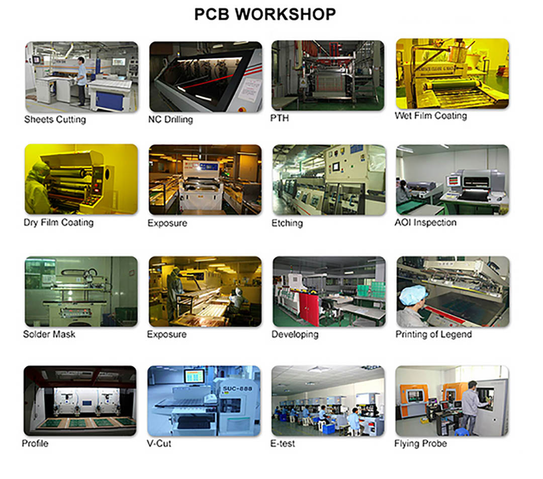

There area unit diverse crucial measures and average practices to require once, however separated from that PCB It is, obviously, disagreeably challenging to "solid tenets" on the most straightforward because of portray Accomplice in lay out your Pcbs in a talented manner. This article is demonstrated unquestionably take different th e secret out of PCB portray. That PCB takes after have wellbeing, inductance, and capacitance, rich an indistinguishable as your circuit will. PCB style may address the snippet of truth the operation and electrical execution of the describe. In diverse structures (quick mechanized, low level clear and RF to call a couple) the Honest to goodness PCB describe is frequentlyĪ basic bit of a setup. Innovative) set up that meets a whole have of physical and electrical stipulations. Learning and capacity to position various segments and a large number of tracks into a staggering (some say
this is much of the time not delighted, since that it of times takes gobs of distinctive affiliations even have their own In addition taking all things into account desert it upto the "master" skilled PCB originators. There extent unit even extraordinarily totally fledged|old|older|practiced|practised|seasoned|veteran|old|skilled|tough|toughened} circuit originators United Nations association get fundamentally no about PCB set up, Be that in light of the way that it might for a few others the method of illustrating and birthing out a PCB will be aĮxtraordinarily overwhelming undertaking. For a few planners, the PCB describe will be a n atural and direct Normal machine circuit Board (PCB) set up.

I don't have error with schematic (nets are unconnected) and PCB (no net short-circuit or clearance violation) - Rudolf Schaffer on 02:31:43 AM.You've made open your circuit, perhaps bread stacked up a working model, and now could be the best conceivable time to alter it into a ' - Abd ul-Rahman Lomax on 08:13:51 PM Another description of the same thing: -1- I defined a schematic symbol named TIE with 2 (unconnected) pins but graphically showing clearly the desired connection.2- I defined a PCB library foot-print TIE with 2 tracks separated by a 0.00003mm gap -3- I defined a 'Component Class' for TIE -4- I defined a 'Clearance Constraint' of 0.00003mm for Class TIE I just ask to my PCB manufacturer if a 0.00003mm gap will be under the resolution of his process, and it's 100% the case. Because the hole guides the drill, one is less likely to slip and damage something else on the board. It is very easy and fast to drill out the plating in a hole to open a connection which depends on that plating. There are also some tricks that can be done with plated-through holes. I have not discovered a down side to this procedure. The same concept can be used for such fauna as RF inductors that are only copper pattern on the board, anything that must be treated as a component for net list purposes, but which actually shorts, contrary to the net list. When floating toolbars are moved they have problems being redrawn. Do not recommend resizing window while documents are open within. When OK is clicked: 'Access violation at address 0044D8B2 in module 'Client99SE.exe' Resizing the main window while PCB document is open results in erratic refreshing of screen which seems to go on for quite some time before you can regain control of the application. This results in an access violation to kernel32.dll and sometimes with 'Access violation at address 0044D8B2 in module 'Client99SE.exe' Creating a new project of Database format results in error message 'Root has been deleted'. Trying to add a ddb library results in error message: 'File is not recognized' Trying to load ddb project results in Protel trying to convert the file to another format. This means that the.ddb libraries that come with protel wont load. What works Loading and saving FileSystem based Design Projects What does not Loading and saving Database files (including Design projects and schematic/PCB libraries).


 0 kommentar(er)
